당신은 주제를 찾고 있습니까 “아두 이노 485 통신 – TTL to RS485 컨버터모듈 아두이노에 활용하기!“? 다음 카테고리의 웹사이트 sk.taphoamini.com 에서 귀하의 모든 질문에 답변해 드립니다: https://sk.taphoamini.com/wiki/. 바로 아래에서 답을 찾을 수 있습니다. 작성자 DeviceMart 이(가) 작성한 기사에는 조회수 4,573회 및 좋아요 46개 개의 좋아요가 있습니다.
Table of Contents
아두 이노 485 통신 주제에 대한 동영상 보기
여기에서 이 주제에 대한 비디오를 시청하십시오. 주의 깊게 살펴보고 읽고 있는 내용에 대한 피드백을 제공하세요!
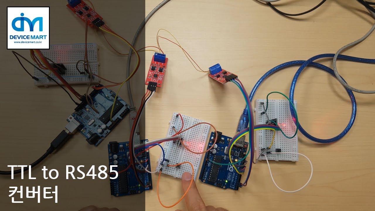
d여기에서 TTL to RS485 컨버터모듈 아두이노에 활용하기! – 아두 이노 485 통신 주제에 대한 세부정보를 참조하세요
TTL to RS485 컨버터 사용 방법에 대해 설명합니다.
[디바이스마트]TTL to RS485 자동 흐름제어 컨버터 모듈 [SZH-CVBE-010]http://www.devicemart.co.kr/1324908
아두 이노 485 통신 주제에 대한 자세한 내용은 여기를 참조하세요.
[간단한 아두이노 코딩] 18. RS485 통신 해보기 (TTL … – IT 방랑기
RS485는 이름에서 알 수 있듯, Serial 통신의 하나이다. RS232 혹은 UART와는 달리 오직 2개의 선으로 여러 장치를 병렬로 연결하여 통신할 수 있다는 …
Source: jcdgods.tistory.com
Date Published: 5/17/2022
View: 3327
Arduino를 사용하는 RS-485 구현 – 기린
MAX485 모듈을 사용하여 두 Arduino 간의 통신에서 RS-485 프로토콜을 구현합니다. RS-485는 데이터와 함께 전송되는 동기화 클럭 신호가 없기 때문에 …
Source: fishpoint.tistory.com
Date Published: 8/7/2021
View: 127
아두이노 VS 아두이노 RS485 데이터 송수신 – 블로그 – 네이버
책상 한쪽 구석에서 항상 굴러다니고 있는 아두이노들을 이용해서 RS485 통신으로 데이터를 송수신 해보려고 한다. 아두이노 RS485.
Source: blog.naver.com
Date Published: 8/3/2021
View: 9512
Giao tiếp 32 thiết bị Arduino với RS485 – Điện Tử Hello
-Gửi dữ liệu vào tại chân DI của IC1. -Đọc Dữ liệu Ra tại chân DO của IC2. Module Chuyển Đổi RS-485 to TTL. Ví dụ sơ đồ kết nối RS485 giữa 2 Arduino Uno …
Source: www.dientuhello.com
Date Published: 11/23/2021
View: 9461
Arduino Uno 로 시리얼(Serial) 직렬통신을 해보고 RS485 통신 …
Arduino Uno 로 시리얼(Serial) 직렬통신을 해보고 RS485 통신으로 여러개의 아두이노와 통신해 보기. 오마이엔지니어 2019. 1. 19. 23:13. 반응형. Arduino Uno 로 …
Source: rockjjy.tistory.com
Date Published: 8/12/2021
View: 2751
아두 이노 485 통신 | Sử Dụng Arduino Bằng Chuẩn Rs485 Để …
아두 이노 485 통신 주제에 대한 자세한 내용은 여기를 참조하세요. [간단한 아두이노 코딩] 18. RS485 통신 해보기 (TTL … – IT 방랑기.
Source: you.covadoc.vn
Date Published: 6/6/2021
View: 1878
Modbus (RS-485) Using Arduino – Arduino Project Hub – Cloud
We implement RS-485 protocol in communication between two Arduinos using MAX485 … Simplex communication between two Arduinos by RS485.
Source: create.arduino.cc
Date Published: 2/9/2022
View: 9903
주제와 관련된 이미지 아두 이노 485 통신
주제와 관련된 더 많은 사진을 참조하십시오 TTL to RS485 컨버터모듈 아두이노에 활용하기!. 댓글에서 더 많은 관련 이미지를 보거나 필요한 경우 더 많은 관련 기사를 볼 수 있습니다.
주제에 대한 기사 평가 아두 이노 485 통신
- Author: DeviceMart
- Views: 조회수 4,573회
- Likes: 좋아요 46개
- Date Published: 2019. 10. 30.
- Video Url link: https://www.youtube.com/watch?v=Oqcxw_QdUJU
[간단한 아두이노 코딩] 18. RS485 통신 해보기 (TTL to RS485 컨버터)
728×90
RS485 통신 해보기 (TTL to RS485 컨버터)
1. RS485 통신이란
RS485는 이름에서 알 수 있듯, Serial 통신의 하나이다. RS232 혹은 UART와는 달리 오직 2개의 선으로 여러 장치를 병렬로 연결하여 통신할 수 있다는 장점이 있다. 물론 속도는 느린 편이지만, 선의 개수가 적고 높은 전압(일반적으로 +-12볼트)를 사용하기 때문에 최대 4000피트(약 1.2km)까지 통신할 수 있다.
아래는 RS485의 연결도를 나타낸다.
위 그림에서 알 수 있듯 총 4개의 장치가 같은 A와 B라인에 연결되어 있다. 즉, 한 시점는 반드시 한개의 장치만 데이터를 전송할 수 있다.(half-duplex) 또한 각 장치들은 모두 같은 보 레이트(Buad Rate)와 설정을 가지고 있어야 함을 알 수 있다.
2. TTL to RS485 컨버터
직전 [간단한 아두이노 코딩] 17. USB to TTL 컨버터 사용해보기에서 말했듯 일반적인 TTL 컨버터는 한쪽이 5V 전압을 사용하는 UART 통신을 수행할 수 있음을 뜻한다.
따라서 RS485 통신 테스트를 해보고 싶다면, TTL to RS485 컨버터를 2개 사용하거나 혹은 직전과 같이 TTL to RS485와 RS480 to USB 컨버터를 이용하여 컴퓨터와 연결해서 확인해야 한다.
그리고 컨버터 중에는 A, B 라인이 아닌 R+, T+ R-, T- 총 4개의 라인을 사용하는 제품이 있는데 이 제품은 +라인끼리(R+, T+) 연결하여 A라인으로, -라인끼리(R-, T-) 연결하여 B라인으로 생각하면 된다.
4라인 제품은 2개의 +,- 라인 페어를 통하여 전이중(Full Duplex)할 수 있다. 다만, 대부분의 RS485 장치들이 반이중(Half-duplex)만 지원하는 경우가 많기 때문에 이 포스팅에서는 묶어서 반이중으로 사용한다.
3. 대표적인 RS485 컨버터
왼쪽부터 MAX485 칩셋 기반 TTL 컨버터, 저렴한 USB to RS485(SZH-CVBE-008, CH340 칩셋) 그리고 리얼시스 USB to 485/422 겸용 컨버터이다.
실제로 TTL 컨버터는 모델 실증용으로 사용했고, 좌측 두개는 필드에서 테스트해본 결과 두번째 제품은 저렴한 대신 정말 잘 죽는다. 리얼시스는 제일 비싼만큼 튼튼했지만 너무 비싸다는게 단점.
아무튼 우리는 간단한 통신 테스트를 진행하는 것이므로 TTL to RS485 (MAX485 칩셋) 컨버터를 이용할 것이다.
4. 회로도
회로도와 같이 각 아두이노에 RS485 TTL 컨버터의 RO를 0번(Rx), DI를 1번(Tx) 그리고 RE, DE를 7번에 연결하자.
그리고 두번째 아두이노에는 A5번에 LED를 하나 연결해주자.
그리고 두 컨버터의 A와 B라인을 서로 연결해주자. 교차하는 것이 아니다. (만약 USB 컨버터가 있다면 A 아두이노 대신 USB to RS485 A, B 라인을 연결해주면 된다.)
이제 A 아두이노에서 영어 O와 X를 1초 간격으로 전달 할 것이다. 그러면 B 아두이노는 O와 X를 읽어 LED를 O일 때 켜고 X일 때 끌 것이다. (A는 MASTER/송신, B는 SLAVE/수신)
5. 소스코드
A 아두이노 소스코드
// A 아두이노 마스터 송신 #include
#define ENABLE 7 // RO(Rx-0번), DI(Tx-1번) SoftwareSerial rs485(0,1); void setup() { rs485.begin(9600); pinMode(ENABLE, OUTPUT); // RE/DE에서 Write시에 HIGH // Read시에 LOW이지만, 여기서는 보내기만 한다. digitalWrite(ENABLE, HIGH); } void loop() { rs485.print(‘O’); delay(1000); rs485.print(‘X’); delay(1000); } B 아두이노 소스코드
// B 아두이노 슬레이브 수신 #include
#define ENABLE 7 #define LED 13 // RO(Rx-0번), DI(Tx-1번) SoftwareSerial rs485(0,1); void setup() { rs485.begin(9600); pinMode(ENABLE, OUTPUT); pinMode(LED, OUTPUT); // RE/DE에서 Write시에 HIGH // Read시에 LOW이지만, 여기서는 받기만 한다. digitalWrite(ENABLE, LOW); } void loop() { if(rs485.available()>=1){ char val = rs485.read(); if(val==’O’) digitalWrite(LED, HIGH); else if(val==’X’) digitalWrite(LED, LOW); } } 반응형
Arduino를 사용하는 RS-485 구현
반응형
Arduino를 사용하는 RS-485 구현
MAX485 모듈을 사용하여 두 Arduino 간의 통신에서 RS-485 프로토콜을 구현합니다.
RS-485는 데이터와 함께 전송되는 동기화 클럭 신호가 없기 때문에 비동기 직렬 통신 프로토콜의 한 유형입니다. RS-485는 차동 신호를 사용하여 한 장치에서 다른 장치로 이진 데이터를 전송합니다. 차동 신호는 5V 양과 음을 사용하여 차동 전압을 생성하여 작동했습니다. 이 차동 신호 방법은 공통 모드 노이즈를 거부하는 이점이 있습니다.
RS-485는 최대 30 Mbps의 데이터 전송 속도를 지원합니다. RS-485는 또한 단일 마스터로 많은 슬레이브를 지원합니다. RS-485 프로토콜은 최대 32개의 장치를 연결할 수 있습니다.
이 프로젝트에서는 MAX485 모듈을 사용하여 두 Arduino 간의 통신에서 RS-485 프로토콜을 구현하려고 합니다. 이 모듈은 작동 전압으로 5V를 사용하며 다음 표와 같이 핀아웃 구성이 있습니다.
MAX485 모듈 pinout configuration
RS-485 모듈을 송신기로
송신기로 사용하기 위해서는 RE 핀과 DE 핀을 5V에 연결하고 DI 핀을 TX에 연결해야 합니다. 데이터는 Arduino TX 핀에서 모듈 DI 핀으로 전송되고 데이터는 A, B를 통해 전송됩니다.
송신기가 되는 485 모듈과 아두이노
void setup() { Serial.begin(9600); } void loop() { int lectura = analogRead(0);//leemos el valor del potenciómetro (de 0 a 1023) byte angulo= map(lectura, 0, 1023, 0, 180); // escalamos la lectura a un valor de ángulo (entre 0 y 180) Serial.write(angulo); //enviamos el ángulo correspondiente delay(50); }
수신기로서의 RS-485 모듈
수신기로 사용하기 위해서는 RE 핀과 DE 핀을 GND에 연결하고 RO 핀을 RX에 연결해야 합니다. AB에서 수신한 데이터는 Arduino RX 핀에 연결된 RO 핀으로 전송되어 Arduino에서 데이터를 읽을 수 있습니다. RS-485는 단방향, 반이중 및 전이중의 세 가지 유형의 직렬 통신 시스템으로 구현할 수 있습니다.
수신기가 되는 485 모듈과 아두이노
#include
Servo myservo; // creamos el objeto servo void setup() { Serial.begin(9600); myservo.attach(9); // asignamos el pin 9 para el servo. } void loop() { if (Serial.available()) { int angulo = Serial.read(); //Leemos el dato recibido if(angulo<=180) //verificamos que sea un valor en el rango del servo { myservo.write(angulo); //movemos el servomotor al ángulo correspondiente. } } } RS485를 통한 두 Arduino 간의 Simplex Communication Simplex 통신은 단방향 통신(하나는 데이터를 보내고 다른 하나는 데이터만 수신)으로, 하나의 arduino는 송신기로만 작동하고 다른 하나는 수신기로만 작동합니다. 이 실험에서 송신기는 전위차계에서 데이터를 읽어 수신기에 연결된 서보 모터를 제어합니다. 동작 코드는 위의 송신기 동작 코드와 수신기 동작 코드를 사용하시면 동작합니다. https://naylampmechatronics.com/blog/37_comunicacion-rs485-con-arduino.html RS485를 통한 두 Arduino 간의 Half-duplex 통신 반이중 통신은 데이터를 동시에 주고받을 수 없는 한 채널을 사용하는 양방향 통신입니다. 두 arduino 모두 GPIO 핀에 의해 제어되는 송신기 또는 수신기로 교대로 동작합니다(HIGH는 송신기로 활성화하고 LOW는 수신기로 활성화). https://naylampmechatronics.com/blog/37_comunicacion-rs485-con-arduino.html 반이중 통신에서는 단일 채널을 사용하여 통신합니다. 한 지점에서는 채널을 통해 데이터가 전송되고 다른 순간에는 데이터가 수신되지만 동시에 송수신할 수는 없습니다. 이 통신을 수행하려면 RS485 모듈의 DE 및 RE 핀을 Arduino에 연결해야 합니다. 이를 통해 프로그램에서 모듈을 송신기 또는 수신기로 설정할 수 있습니다. 이 실험에서 Arduino 1은 Arduino 2에 연결된 서보 모터를 제어하기 위해 전위차계에서 데이터를 읽을 뿐만 아니라 Arduino 2에 연결된 센서(전위차계로 표시됨)에서 데이터를 수신한 다음 데이터가 임계값에 도달했습니다. 연결은 아래와 같습니다. https://naylampmechatronics.com/blog/37_comunicacion-rs485-con-arduino.html 왼쪽의 아두이노는 Master가 되고, 오른쪽의 Arduino는 슬레이브가 됩니다. 코드를 마스터와 슬레이브 둘 다 표시합니다. 마스터 코드 const int ledPin = 13; // Numero del pin para el Led const int EnTxPin = 2; // HIGH:TX y LOW:RX void setup() { Serial.begin(9600); Serial.setTimeout(100);//establecemos un tiempo de espera de 100ms //inicializamos los pines pinMode(ledPin, OUTPUT); pinMode(EnTxPin, OUTPUT); digitalWrite(ledPin, LOW); digitalWrite(EnTxPin, HIGH); } void loop() { int lectura = analogRead(0);//leemos el valor del potenciómetro (de 0 a 1023) int angulo= map(lectura, 0, 1023, 0, 180);// escalamos la lectura a un valor de ángulo (entre 0 y 180) //---enviamos el ángulo para mover el servo------ Serial.print("I"); //inicio de trama Serial.print("S"); //S para indicarle que vamos a mover el servo Serial.print(angulo); //ángulo o dato Serial.print("F"); //fin de trama //---------------------------- delay(50); //---solicitamos una lectura del sensor---------- Serial.print("I"); //inicio de trama Serial.print("L"); //L para indicarle que vamos a Leer el sensor Serial.print("F"); //fin de trama Serial.flush(); //Esperamos hasta que se envíen los datos //----Leemos la respuesta del Esclavo----- digitalWrite(EnTxPin, LOW); //RS485 como receptor if(Serial.find("i"))//esperamos el inicio de trama { int dato=Serial.parseInt(); //recibimos valor numérico if(Serial.read()=='f') //Si el fin de trama es el correcto { funcion(dato); //Realizamos la acción correspondiente } } digitalWrite(EnTxPin, HIGH); //RS485 como Transmisor //----------fin de la respuesta----------- } void funcion(int dato) { if(dato>500) digitalWrite(ledPin, HIGH); else digitalWrite(ledPin, LOW); } 슬레이브 코드
#include
Servo myservo; // creamos el objeto servo const int EnTxPin = 2; void setup() { Serial.begin(9600); myservo.attach(9); // asignamos el pin 9 para el servo. pinMode(EnTxPin, OUTPUT); digitalWrite(EnTxPin, LOW); //RS485 como receptor } void loop() { if(Serial.available()) { if(Serial.read()==’I’) //Si recibimos el inicio de trama { char funcion=Serial.read();//leemos el carácter de función //—Si el carácter de función es una S entonces la trama es para mover el motor———– if(funcion==’S’) { int angulo=Serial.parseInt(); //recibimos el ángulo if(Serial.read()==’F’) //Si el fin de trama es el correcto { if(angulo<=180) //verificamos que sea un valor en el rango del servo { myservo.write(angulo); //movemos el servomotor al ángulo correspondiente. } } } //---Si el carácter de función es L entonces el maestro está solicitando una lectura del sensor--- else if(funcion=='L') { if(Serial.read()=='F') //Si el fin de trama es el correcto { int lectura = analogRead(0); //realizamos la lectura del sensor digitalWrite(EnTxPin, HIGH); //rs485 como transmisor Serial.print("i"); //inicio de trama Serial.print(lectura); //valor del sensor Serial.print("f"); //fin de trama Serial.flush(); //Esperamos hasta que se envíen los datos digitalWrite(EnTxPin, LOW); //RS485 como receptor } } } } delay(10); } 참고 COMUNICACIÓN RS485 CON ARDUINO Modbus (RS-485) Using Arduino 위 사이트를 참고하여 전체를 다시 포스팅하기로~^^ 반응형
아두이노 VS 아두이노 RS485 데이터 송수신
임베디드 아두이노 VS 아두이노 RS485 데이터 송수신 DAON ・ URL 복사 본문 기타 기능 공유하기 신고하기 책상 한쪽 구석에서 항상 굴러다니고 있는 아두이노들을 이용해서 RS485 통신으로 데이터를 송수신 해보려고 한다. 아두이노 RS485 사실 뭔가를 하나 만들어보고 싶은 게 있는데 간단한 거라서 아두이노를 이용해서 몇 가지 테스트를 해보고 간단한 보드를 설계해서 만들 생각이다. 아두이노와 RS485 만들고자 하는 것은 Master에서 다수의 Slave에 특정 값을 던져주면 그 값에 따라 Slave들이 각자 맞은 역할을 수행하도록 하는 것이며 실행하는 역할은 모두 다르다. 구상도 예를 들어 만약 마스터에서 ‘A’를 전송하면 슬레이브 1은 10초간 LED를 켜고 슬레이브 2는 5초간 모터를 돌리는 등등 각자 맞은 역할을 하는 것이다. 그리고 Master와 Slave 간의 거리가 수십 미터까지 멀어질 수도 있을 거 같아서 1.2km까지 통신이 가능하다는 RS485를 이용해보려고 한다. 본격적으로 만들면서 필요한 기능은 추가할 생각이고 오늘은 두 개의 아두이노를 이용해서 하나는 Master 또 다른 하나는 Slave로 사용해보려고 한다. 그런데 아두이노 자체적으로는 rs485를 지원하지 않기 때문에 변환 모듈을 사용해야 하는데 나는 MAX485 TTL to RS-485 컨버터 모듈을 사용해보려고 한다. 이건 아두이노 마다 하나씩 있어야 한다. 변환 모듈 이게 여러 개 있으면 갖고 있는 아두이노를 모두 이용해서 여러 개의 슬레이브를 만들고 싶지만.. 현재 갖고 있는데 두 개밖에 없다.ㅠ.ㅠ 아두이노는 나노까지 몇 개 더 있는데..;; 굴러다니는 아두이노들 일단 오늘은 두 개만 통신해보고… 변환 모듈 몇 개 더 주문해서 다수의 Slave를 구성해봐야겠다. 배선 두 개의 아두이노와 변환 모듈의 배선은 다음과 같다. 배선 RX(아두이노 2번 핀 사용) ▶ RO(변환 모듈) , TX(아두이노 3번 핀 사용) ▶ DI(변환 모듈) , 아두이노 7번 핀 ▶ DE & RE 그리고 모듈의 VCC와 GND는 아두이노의 VCC, GND를 각각 연결하고 모듈의 A와 B를 서로 연결해준다. DI, DE, RE, RO GND, A, B PIN 중 DE와 RE는 묶어서 7번 핀에 연결을 했는데 7번 핀을 OUTPUT 모드로 설정한다. 그리고 데이터를 전송하기 위해서는 ‘HIGH’를 수신하기 위해서는 ‘LOW’ 값을 주면 된다. 이제 Master의 코드부터 작성해보자. (코드는 데이터 송수신에만 중점을 두고 대충 작성함.) #include
#define RS485Control 7 //전송 HIGH, 수신 LOW SoftwareSerial rs485(2, 3); //RX-RO, TX-DI char set[] = {‘A’, ‘B’, ‘C’, ‘D’}; void setup() { Serial.begin(9600); Serial.write(“====Master START=== “); rs485.begin(9600); pinMode(RS485Control, OUTPUT); //Control Pin Mode } void loop() { int i = 0; digitalWrite(RS485Control, HIGH); //송신모드 if (rs485.available()) { delay(100); for (i = 0; i < sizeof(set); i++) { rs485.write(set[i]); //순서대로 문자 전송 Serial.write(set[i]); Serial.write(" 전송완료 "); //시리얼 모니터를 통해 전송확인 delay(2000); } } } char 배열에 네 개의 문자를 저장하고 이것들을 순서대로 전송하고 있다. 그리고 전송된 데이터를 수신하는 Slave의 코드 내용은 아래와 같다. #include
#include #include #define RS485Control 7 //전송 HIGH, 수신 LOW SoftwareSerial rs485(2, 3); //RX-RO, TX-DI char buff[50]; //수신된 문자 저장할 버퍼, 문자열 저장 void setup() { Serial.begin(9600); Serial.write(“====Slave START=== “); rs485.begin(9600); pinMode(RS485Control, OUTPUT); //Control Pin Mode } void loop() { int i = 0; digitalWrite(RS485Control, LOW); //수신모드 if (rs485.available()) { while (rs485.available() && i < 50) { buff[i++] = rs485.read(); //전송된 문자 버퍼에 저장 } } buff[i++] = '\0'; //마지막에 null 문자 입력 if (i > 0) { //수신된 데이터가 있다면 내용 출력하고 비교 Serial.write(buff); Serial.write(”
“); if (!strcmp(buff, “A”)) { // 문자열 비교 Serial.write(buff); Serial.write(” 수신됨
“); } else { Serial.write(“A가 아닙니다.
“); } }else{ Serial.write(“수신된 데이터 없음
“); } delay(2000); } 문자 하나씩을 수신해서 버퍼에 저장하는데 수신된 내용에 따라 특정 작업을 실행할 수 있도록 ‘A’가 전송되는 순간을 잡아본다. 각각의 아두이노에 코드를 올린 후 실행하면 시리얼 모니터에서 다음과 같은 결과를 확인할 수 있다. 아두이노 rs485 통신 실행 결과 COM3에 연결된 Master는 2초 간격으로 문자 하나씩을 전송하며 COM13에 연결된 Slave에서는 수신 받은 데이터를 버퍼에 저장했다가 출력하고 있으며 수신된 값이 ‘A’일 때를 체크해보고 있다. 이렇게 해서 아두이노 두 개를 이용해서 RS485 통신으로 데이터를 송수신 해봤는데 간단한 내용이지만 아두이노로는 아직 구현해본 적이 없어서 나름대로 정리하면서 테스트를 해봤다. 인쇄
Giao tiếp 32 thiết bị Arduino với RS485
RS485 LÀ GÌ
Năm 1983, Hiệp hội công nghiệp điện tử (EIA) đã phê duyệt một tiêu chuẩn truyền cân bằng mới gọi là RS-485. Đã được chấp nhận rộng rãi và sử dụng trong công nghiệp, y tế, và dân dụng. Có thể coi chuẩn RS485 là một phát triển của RS232 trong việc truyền dữ liệu nối tiếp. Những bộ chuyển đổi RS232/RS485 cho phép người dùng giao tiếp với bất kỳ thiết bị mà sử dụng liên kết nối tiếp RS232 thông qua RS485. Liên kết RS485 được hình thành cho việc thu nhận dữ liệu ở khoảng cách xa và điều khiển cho những ứng dụng. Những đặc điểm nổi trội của RS485 là nó có thể hỗ trợ một mạng lên tới 32 trạm thu phát trên cùng một đường truyền, tốc độ baud có thể lên tới 115.200 cho một khoảng cách là 4000feet (1200m).
Với kiểu truyền cân bằng và các dây được xoắn lại với nhau nên khi nhiễu xảy ra ở dây này thì cũng xảy ra ở dây kia, tức là hai dây cùng nhiễu giống nhau. Điều này làm cho điện áp sai biệt giữa hai dây thay đổi không đáng kể nên tại nơi thu vẫn nhận được tín hiệu đúng nhờ tính năng đặc biệt của bộ thu đã loại bỏ nhiễu. Liên kết RS485 được sử dụng rất rộng rãi trong công nghiệp, nơi mà môi trường nhiễu khá cao và sự tin tưởng vào tính ổn định của hệ thống là điều quan trọng. Bên cạnh đó khả năng truyền thông qua khoảng cách xa ở tốc độ cao cũng rất được quan tâm, đặc biệt là tại những nơi mà có nhiều trạm giao tiếp được trải ra trên diện rộng.
Module Chuyển Đổi RS-485 to TTL
Module giúp chuyển đổi mức điện áp TTL sang giao tiếp RS-485.
Module được thiết kế nhỏ gọn, tích hợp các linh kiện cần thiết để đảm bảo tốc độ truyền dẫn cao, khoảng cách truyền xa mà vẫn ổn định.
Ứng dụng:
– Truyền thông tín hiệu điều khiển chuẩn RS-485 giữa các vi điều khiển với nhau và với máy tính.
Thông Số Kĩ Thuật:
– Module chuyển đổi TTL sang RS-485 dùng chip Max 485.
– Điện áp hoạt động 5 V (mức TTL)
– Kiểu kết nối hàng rào cắm 4 chân ngõ vào (RO, RE, DE ,DI của chip Max485), 4 chân ngõ ra(VCC, GND, A, B).
– Tốc độ truyền tối đa 2Mbps, khoảng cách tối đa 1Km.
Sơ đồ chân MAX485:
Chức năng MAX485:
Max485 là bộ truyền nhận dữ liệu năng lượng thấp dùng cho chuẩn RS485.
Tốc độ bit Max= 2,5Mbps
Có thể kết nối tối đa 32 thiết bị trên bus 485 .
Điện áp hoạt động : -7V ~ 12V.
Thường dùng 5V.
Bus Max485 truyền dữ liệu Vi sai bằng 2 dây A, B nên khoảng cách truyền lớn, khả năng chống nhiễu tốt.
-với A-B > 200mV sẽ tạo mức logic 1.
-với B-A > 200mV sẽ tạo mức logic 0.
Ứng dụng thực tế:
– Giao tiếp giữa hai thiết bị. Có thể giao tiếp tối đa 32 MAX485 với nhau trên cùng một BUS.
– Để giao tiếp các MAX485 với nhau chúng ta cần kết nối các chân với nhau A nối với A B nối với B
Truyền giữ liệu MAX458.
Để Truyền dữ liệu với Max485 cần thực hiện các bước sau.
-Kết nối chân A với A, B với B giữa 2 IC.
-Cấu hình truyền trên IC1, cho chân DE mức 1.
-Cấu hình nhận trên IC2, cho chân RE mức 0.
-Gửi dữ liệu vào tại chân DI của IC1.
-Đọc Dữ liệu Ra tại chân DO của IC2.
Ví dụ sơ đồ kết nối RS485 giữa 2 Arduino Uno
Giao tiếp RS485 giữa Uno và Nano
Module RS-485 – Arduino UNO (Master):
RS-485 Arduino UNO DI 1 (TX) DE RE 8 R0 0 (RX) VCC 5V GND GND A To A of Slave RS-485 B To B of Slave RS-485
Module RS-485 – Arduino Nano (Slave):
RS-485 Arduino UNO DI D1 (TX) DE RE D8 R0 D0 (RX) VCC 5V GND GND A To A of Master RS-485 B To B of Master RS-485
Màn hình16x2 LCD kết nối Arduino Nano:
16×2 LCD Arduino Nano VSS GND VDD +5V V0 Nối đến biến trở để điều chỉnh độ tương phản LCD RS D2 RW GND E D3 D4 D4 D5 D5 D6 D6 D7 D7 A +5V K GND
Một 10K biến trở nối vào Pin A0 của Arduino UNO và một LED được kết nối đến pin D10 của Arduino Nano.
Code chương trình:
Master (Arduino UNO): //Master code (Arduino UNO)
//Serial Communication Between Arduino using RS-485 int enablePin = 8;
int pushval = A0;
int potval =0 ; void setup()
{
Serial.begin(9600); // initialize serial at baudrate 9600:
pinMode(enablePin, OUTPUT);
pinMode(pushval,INPUT);
delay(10);
digitalWrite(enablePin, HIGH); // (always high as Master Writes data to Slave)
}
void loop()
{
int potval = analogRead(pushval);
Serial.println(potval); //Serial Write POTval to RS-485 Bus
delay(100);
} SLAVE CODE: (Arduino NANO): //Slave code (Arduino NANO)
//Serial Communication Between Two Arduinos using RS-485
//Circuit Digest #include
//Include LCD library for using LCD display functions int enablePin = 8; int ledpin = 10; LiquidCrystal lcd(2,3,4,5,6,7); // Define LCD display pins RS,E,D4,D5,D6,D7 void setup()
{
lcd.begin(16,2);
lcd.print(“CIRCUIT DIGEST”);
lcd.setCursor(0,1);
lcd.print(“RS485 ARDUINO”);
delay(3000);
lcd.clear();
Serial.begin(9600); // initialize serial at baudrate 9600:
pinMode(ledpin,OUTPUT);
pinMode(enablePin, OUTPUT);
delay(10);
digitalWrite(enablePin, LOW); // (Pin 8 always LOW to receive value from Master) } void loop() {
while (Serial.available()) //While have data at Serial port this loop executes
{
lcd.clear();
int pwmval = Serial.parseInt(); //Receive INTEGER value from Master throught RS-485
int convert = map(pwmval,0,1023,0,255); //Map those value from (0-1023) to (0-255)
analogWrite(ledpin,convert); //PWM write to LED
lcd.setCursor(0,0);
lcd.print(“PWM FROM MASTER”);
lcd.setCursor(0,1);
lcd.print(convert); //Displays the PWM value
delay(100);
}
}
Code chương trình giao tiếp RS485 nhiều Arduino
Code cho thiết bị Master:
#include
//Khai báo thư viện I2C LCD 16×2 LiquidCrystal_I2C lcd(0x27,16,2); // Cấu hình địa chỉ I2C cho LCD 16×2 là 0x27 int value1 = 0, value2 = 0; const int LED = 13; const int Enable = 2; void setup() { Serial.beg 9600); Serial.setTimeout(250); pinMode(LED, ); pinMode(Enable, ); digitalWrite(LED, LOW); digitalWrite(Enable, HIGH); lcd.init(); lcd.backlight(); } void loop() { Serial.p “I” ); Serial.p “1” ); Serial.p “L” ); Serial.p “F” ); Serial.flush(); digitalWrite(Enable, LOW); (Serial.find( “i” )) { int slave1 = Serial.pars ); value1 = Serial.pars ); (Serial.read() == ‘f’ && slave1 == 1) { lcd.setCursor(0,0); lcd.p “Escravo 1: ” ); lcd.setCursor(11,0); lcd.p value1); } } digitalWrite(Enable, HIGH); Serial.p “I” ); Serial.p “2” ); Serial.p “L” ); Serial.p “F” ); Serial.flush(); digitalWrite(Enable, LOW); (Serial.find( “i” )) { int slave2 = Serial.pars ); value2 = Serial.pars ); (Serial.read() == ‘f’ && slave2 == 2) { lcd.setCursor(0,1); lcd.p “Escravo 2: ” ); lcd.setCursor(11,1); lcd.p value2); } } digitalWrite(Enable, HIGH); } Code chương trình cho các Slave:
Slave 1:
const int Enable = 2 ; const int SlaveNumber = 1 ; void setup () { Serial . begin ( 9600 ); Serial . setTimeout ( 250 ); pinMode (Enable, OUTPUT ); digitalWrite (Enable, LOW ); pinMode ( 13 , OUTPUT ); pinMode (A0, INPUT ); } void loop () { if ( Serial . available ()) { if ( Serial . read ()== ‘I’ ) { int Slave = Serial . parseInt (); if (Slave == SlaveNumber) { char command = Serial . read (); if (command == ‘L’ ) { if ( Serial . read ()== ‘F’ ) { int AnalogValue = analogRead ( 0 ); digitalWrite (Enable, HIGH ); Serial . print ( “i” ); Serial . print (SlaveNumber); Serial . print (AnalogValue); Serial . print ( “f” ); Serial . flush (); digitalWrite (Enable, LOW ); } } } } } delay ( 10 ); }
Tương tự cho Slave 2, 3, 4…32 chúng ta chỉ cần thay
const int SlaveNumber = 2;
bằng các giá trị thay đổi tương ứng.
Tham khảo:
https://www.hackster.io
https://circuitdigest.com/
Arduino Uno 로 시리얼(Serial) 직렬통신을 해보고 RS485 통신으로 여러개의 아두이노와 통신해 보기
반응형
Arduino Uno 로 시리얼(Serial) 직렬통신을 해보고 RS485 통신으로 동시에 여러개의 아두이노와 통신해 보는 프로젝트 입니다
시리얼통신 이란?
임베디드 시스템은 각종 프로세서와 회로들 간에 서로 통신하며 데이터를 주고 받는것이 기본입니다
임베디드 시스템에서 데이터를 주고 받을때 주로 사용하는 통신방법에는 크게 패러럴(병렬, parallel)과 시리얼(직렬, serial) 통신 방식이 있습니다
패러럴(Parallel) 통신방식은 다수의 비트(bit)를 한번에 전송하는 방법입니다
보통 8 또는 16 또는 그 이상의 라인을 통해 동시에 데이터를 보내줍니다
타이밍(clock)에 맞춰 모든 라인이 같이 동작할 수 있도록 clock(CLK) 라인이 필요하므로 8-bit data bus 의 경우 9라인이 사용됩니다
시리얼(Serial) 통신방식은 데이터를 스트림으로 바꿔서(직렬화, serialization) 한 번에 한 비트씩 전송합니다
시리얼 통신은 clock 라인을 포함 2라인으로 데이터를 전송할 수 있습니다
1.직렬 통신은 하나 또는 두 개의 전송 라인을 사용하여 데이터를 송수신하는 통신 방법으로, 한 번에 한 비트 씩 데이터를 지속적으로 주고 받습니다
적은 신호선으로 연결이 가능하기 때문에 선재와 중계 장치의 비용이 억제되는 등의 장점이 있습니다
2. 시리얼 통신 규격
RS-232C / RS-422A / RS-485는 EIA (전자 산업 협회) 통신 표준입니다
이러한 통신 표준 중 RS-232C는 다양한 응용 분야에서 널리 채택되어 왔으며 컴퓨터의 표준 장비이기도합니다
모뎀 및 마우스 연결에 사용됩니다. 센서 및 액추에이터에는 이러한 인터페이스가 포함되어 있으며 대부분이 직렬 통신을 통해 제어 할 수 있습니다
RS-232C
이 직렬 통신 표준은 널리 사용되며 종종 표준으로 컴퓨터에 장착됩니다.”EIA-232″라고도합니다
신호선과 커넥터의 목적과 타이밍이 정의되었습니다 (D-sub 25 핀 또는 D- sub 9 핀).
현재 표준은 신호선을 추가하여 개정되었으며 정식으로 “ANSI / EIA-232-E”라고합니다. 그러나 지금은 일반적으로 “RS-232C”라고도합니다
RS-422A
이 표준은 짧은 전송 거리 및 느린 전송 속도와 같은 RS-232C 문제를 수정합니다, “EIA-422A”라고도합니다.
신호선의 목적과 타이밍은 정의되었지만 커넥터는 아닙니다. 많은 호환 제품 주로 D-sub 25 핀 및 D-sub 9 핀 커넥터를 사용합니다
RS-485
이 표준은 RS-422A에서 몇 가지 연결 장치의 문제점을 수정합니다, “EIA-485″라고도합니다
RS-485는 RS-422A와 호환 가능한 표준입니다.
신호선의 목적과 타이밍이 정의되지만 커넥터 대부분의 호환 제품은 주로 D-sub 25 핀 및 D-sub 9 핀 커넥터를 채택합니다
RS-485 (EIA-485 표준)는 RS-422보다 개선된 버전으로, 디바이스 수를 10개에서 32개로 늘리고 최대 부하에서 적절한 신호 전압을 보장하는 데 필요한 전기적 특성을 정의합니다. 이 강화된 멀티드롭(multidrop) 기능으로 단일 RS485 시리얼 포트에 연결된 디바이스의 네트워크를 생성할 수 있습니다. PC에 네트워크 연결된 여러 분산 디바이스가 필요하거나 데이터 수집, HMI 또는 기타 작업을 위해 컨트롤러를 필요로 하는 산업용 어플리케이션에 있어, 노이즈 제거 및 멀티드롭 (multidrop) 기능을 갖춘 RS485는 최상의 선택입니다. RS-485는 RS-422의 상위 집합이므로, 모든 RS-422 장치는 RS-485로 제어할 수 있습니다. RS-485 하드웨어는 최대 4000 피트 케이블을 통한 시리얼 통신에 사용될 수 있습니다.
RS485의 가장 큰 장점은 역시 32개의 디바이스와 통신할 수 있는 멀티드롭 기능입니다
사용된부품
Arduino Uno Italy
미니 브래드보드
점퍼케이블
RS485 to TTL 시리얼 컨버터
UBS to RS485 변환 컨버터
구성 배선도-RS485 시리얼 통신해 보기 (여러개의 아두이노와 통신해 보기)
사용된 예제코드
RS485 example code.txt
테스트방법
위 배선도를 참조하여 USB to RS485 모듈 과 RS485 to TTL 모듈 을 사용해서 일단 한개의 아두이노로 RS485 통신을 해봅니다
배선후 PC의 장치관리자를 확인해 보면 USB to RS485 의 COM포트는 COM9 , 아두이노의 COM포트는 COM5 인것을 확인 할 수 있습니다
아두이노에 위 첨부된 ‘RS485 example code’ 를 컴파일 업로드해 줍니다
아두이노 IDE 2개를 실행 시키고 시리얼 모니터를 COM9 와 COM5 각각 2개를 열어 줍니다
RS485 통신을 할 것이므로 USB to RS485 의 COM포트인 COM9 의 시리얼 모니터의 콘솔 입력창에 원하는 메세지를 입력합니다
그러면 RS485 to TTL 컨버터를 통해 TTL레벨로 변환되어 아두이노의 COM5 시리얼 모니터에 데이터가 전송되어 출력됩니다
여러개(본 테스트 에서는 2개로 테스트 하였습니다) 의 아두이노와 동시에 통신하는 방법도 동일하게 테스트 하면 됩니다
여러개(2개)의 아두이노 배선후 PC의 장치관리자를 확인해 보면
USB to RS485 의 COM포트는 COM83 , 아두이노의 COM포트는 COM5 와 COM7 인것을 확인 할 수 있습니다
여러개(2개)의 아두이노에 위 첨부된 ‘RS485 example code’ 를 컴파일 업로드해 줍니다
아두이노 IDE 3개를 실행 시키고 시리얼 모니터를 COM83 과 COM5 COM7 각각 3개를 열어 줍니다
RS485 통신을 할 것이므로 USB to RS485 의 COM포트인 COM83 의 시리얼 모니터의 콘솔 입력창에 원하는 메세지를 입력합니다
그러면 RS485 to TTL 컨버터를 통해 TTL레벨로 변환되어 아두이노의 COM5 과 COM7 시리얼 모니터에 데이터가 전송되어 출력됩니다
예제코드 입니다
#define SerialTxControl 10 //RS485 제어 접점 핀 arduino pin 10
#define RS485Transmit HIGH
#define RS485Receive LOW
char buffer[100];
void setup(void) {
Serial.begin(9600);
pinMode(SerialTxControl, OUTPUT);
digitalWrite(SerialTxControl, RS485Transmit);
Serial.println(“TEST”);
delay(100);
digitalWrite(SerialTxControl, RS485Receive);
} void loop(void) {
digitalWrite(SerialTxControl, RS485Receive); // 포트에서 데이터를 읽음
int i=0; if(Serial.available()){delay(100);
while( Serial.available() && i< 99) { buffer[i++] = Serial.read();} buffer[i++]='\0';} if(i>0)
{
Serial.println(buffer); // 다른 장치로 출력
} }
프로젝트 동영상-RS485 시리얼 통신해 보기
프로젝트 동영상-RS485 시리얼 통신해 보기 (여러개의 아두이노와 통신해 보기)
위 테스트에서는 RS485통신으로 RS485 모듈에서 데이터를 송신하고 아두이노 우노에서 데이터를 수신을 하였는데요
반대로 아두이노 우노에서 데이터를 송신하고 RS485 모듈에서 데이터를 받을수도 있습니다
Arduino Uno로 RS485 to TTL 모듈과 USB to RS485 모듈을 사용해서 마스터&슬레이브로 통신해 보기
방법은 간단합니다, 위 테스트와 배선도 동일하게 하고 예제도 동일하게 첨부된 예제를 업로드 하면 되지만
예제코드에서 아래 부분을
#define RS485Transmit HIGH
#define RS485Receive LOW
#define RS485Transmit LOW
#define RS485Receive HIGH
이렇게 수정해 주면 됩니다
프로젝트 동영상-Arduino Uno 로 USB to RS485 & RS485 to TTL 모듈을 사용해서 마스터&슬레이브로 데이터 주고 받기
반응형
아두 이노 485 통신 | Sử Dụng Arduino Bằng Chuẩn Rs485 Để Điều Khiển Đèn Có Nút Nhấn 189 개의 가장 정확한 답변
당신은 주제를 찾고 있습니까 “아두 이노 485 통신 – SỬ DỤNG ARDUINO BẰNG CHUẨN RS485 ĐỂ ĐIỀU KHIỂN ĐÈN CÓ NÚT NHẤN“? 다음 카테고리의 웹사이트 you.covadoc.vn 에서 귀하의 모든 질문에 답변해 드립니다: https://you.covadoc.vn/blog. 바로 아래에서 답을 찾을 수 있습니다. 작성자 Le Quoc Thinh 이(가) 작성한 기사에는 조회수 209회 및 좋아요 5개 개의 좋아요가 있습니다.
여기에서 이 주제에 대한 비디오를 시청하십시오. 주의 깊게 살펴보고 읽고 있는 내용에 대한 피드백을 제공하세요!
RS485 통신 해보기 (TTL to RS485 컨버터) 1. RS485 통신이란 RS485는 이름에서 알 수 있듯, Serial 통신의 하나이다. RS232 혹은 UART와는 달리 오직 …
+ 여기에 보기
Source: jcdgods.tistory.com
Date Published: 3/1/2021
View: 7686
MAX485 모듈을 사용하여 두 Arduino 간의 통신에서 RS-485 프로토콜을 구현합니다. RS-485는 데이터와 함께 전송되는 동기화 클럭 신호가 없기 때문에 …
+ 여기에 더 보기
Source: fishpoint.tistory.com
Date Published: 9/21/2021
View: 7246
-Đọc Dữ liệu Ra tại chân DO của IC2. Module Chuyển Đổi RS-485 to TTL. Ví dụ sơ đồ kết nối RS485 giữa 2 Arduino Uno …
+ 더 읽기
Source: www.dientuhello.com
Date Published: 6/6/2021
View: 2437
-RS485모듈의 DI핀은 input으로 TTL통신에 RX에 해당된다. … -쫄병 아두이노는 D4포트에 빨간색LED가 하나 설치되어있다. … -0을 마스터에게 전송하면 …
+ 여기에 자세히 보기
Source: bota.tistory.com
Date Published: 10/10/2021
View: 3167
Arduino Uno 로 시리얼(Serial) 직렬통신을 해보고 RS485 통신으로 여러개의 아두이노와 통신해 보기. 오마이엔지니어 2019. 1. 19. 23:13. 반응형. Arduino Uno 로 …
+ 더 읽기
Source: rockjjy.tistory.com
Date Published: 2/2/2022
View: 3722
We implement RS-485 protocol in communication between two Arduinos using MAX485 … Simplex communication between two Arduinos by RS485.
+ 여기에 표시
Source: create.arduino.cc
Date Published: 4/26/2021
View: 3397
RS-485 통신모듈 / RS485 / 아두이노. 구매 21(남은수량 69개). 6,800원.
+ 자세한 내용은 여기를 클릭하십시오
Source: itempage3.auction.co.kr
Date Published: 7/2/2021
View: 4664
Ví dụ dưới đây sẽ sử dụng Serial Monitor để truyền dữ liệu từ Arduino Master thông qua module RS485 đến arduino ở xa (Remote) và …
+ 여기를 클릭
Source: arduino.vn
Date Published: 6/18/2022
View: 2260
주제와 관련된 더 많은 사진을 참조하십시오 SỬ DỤNG ARDUINO BẰNG CHUẨN RS485 ĐỂ ĐIỀU KHIỂN ĐÈN CÓ NÚT NHẤN. 댓글에서 더 많은 관련 이미지를 보거나 필요한 경우 더 많은 관련 기사를 볼 수 있습니다.
const int Enable = 2 ; const int SlaveNumber = 1 ; void setup () { Serial . begin ( 9600 ); Serial . setTimeout ( 250 ); pinMode (Enable, OUTPUT ); digitalWrite (Enable, LOW ); pinMode ( 13 , OUTPUT ); pinMode (A0, INPUT ); } void loop () { if ( Serial . available ()) { if ( Serial . read ()== ‘I’ ) { int Slave = Serial . parseInt (); if (Slave == SlaveNumber) { char command = Serial . read (); if (command == ‘L’ ) { if ( Serial . read ()== ‘F’ ) { int AnalogValue = analogRead ( 0 ); digitalWrite (Enable, HIGH ); Serial . print ( “i” ); Serial . print (SlaveNumber); Serial . print (AnalogValue); Serial . print ( “f” ); Serial . flush (); digitalWrite (Enable, LOW ); } } } } } delay ( 10 ); }
while (Serial.available()) //While have data at Serial port this loop executes
(1971) 분류 전체보기 녹칸다 (82) 녹칸다의 프로젝트 목록 (21) 녹칸다의잡학사전 (13) 녹칸다의 개발환경 (5) 나름대로요약하고있음 (30) 방과후활동 (11) 녹칸다굿즈 (2) (700) 프로그래밍 아두이노병법서 (8) 아두이노시작하기 (11) C# 호작질 (78) (156) 아두이노 호작질 학생들이해볼만한주제 (23) ESP8266 & Websocket (16) 로터리엔코더와 메뉴트리 (8) N채널릴레이와 자동화매크로 (12) ESP8266 & OTA (5) TCP&UDP (22) RS485모드버스(modbus) (23) MISOL기상관측소 (8) 로라(LoRa)SX1276 (10) 앱인벤터 (31) 노드레드(node-red) (31) nRF24L01 (16) OBD2 (5) 블루투스통신 (20) ESP8266 OPENAPI (18) ESP8266 MQTT (36) ESP8266웹서버 (28) CAN통신(MCP2515) (6) C# HttpListener (8) C# OPENAPI (17) C# MYSQL (16) C# ESP32CAM(IPCAM) (7) A4988과 NEMA17 (11) 타이젠과ESP8266 (10) IoT가습기 (4) Blynk와 ESP8266 (9) Home Assistant (24) ESPNOW (10) LoRa(E220-900T30D) (12) 정보글 (371) 유튜브방송(OBS) (7) 고양이간식 (10) 맛집 (45) 애드센스 (6) 토렌트추천 (2) 알리에서구입한 이상한물건 (17) 블랙박스조사 (2) 천상비연구소 (188) 천상비연구소(이벤트박제) (17) 핫플360이 간다! (30) 모바일핫플지도 (1) 창원 (27) 전국축제지도 (1) 360 자동차 실내뷰 (55) 기아자동차(2020) (4) 현대자동차(2020) (4) 현대자동차(2019) (15) 기아자동차(2019) (4) 쉐보레 (7) 지프 (6) 벤츠 (5) 아우디 (2) 폭스바겐 (1) BMW (7) 애니메이션 (6) 원피스 (6) 유머글 스크랩 (3) 유우머 (3) 증류주&담금주 (5) TV방송 (30) 문제적남자 (9) 아는형님 (14) 요리레시피 (7) 짤방저장소 (16) 동물짤 (16) 장면짤 (0) 웃픈짤 (0) 플레시게임 (670) 피하기게임 (7) 퍼즐게임 (9) 리듬게임 (2) 병맛게임 (2) 킬링타임게임 (4) 디펜스게임 (236) 플렛포머게임 (2) 아케이드게임 (336) 액션게임 (12) 슈팅게임 (43) 날리기게임 (11) 어드벤쳐게임 (6)
RS-485 is one type of asynchronous serial communication protocol because there is no synchronizing clock signal transmitted along with the data. RS-485 uses differential signaling to transfer binary data from one device to another. Differential signaling worked by creating differential voltage using 5V positive and negative.This differential signaling method has the advantage in rejecting common mode noise.
RS-485 supports a maximum data transfer rate of 30 Mbps. RS-485 also supports many slaves with a single master. RS-485 protocol can have up to 32 devices connected.
In this project, we are going to implement RS-485 protocol in communication between two Arduinos using MAX485 module. This module uses 5V as operating voltage and has pinout configuration as shown in the following table.
RS-485 module as transmitter
In order to be used as a transmitter, RE pin and DE pin must be connected to 5V, and DI pin is connected to TX. Data is sent from Arduino TX pin to module DI pin, then data will be sent through AB.
RS-485 module as receiver
In order to be used as a receiver, RE pin and DE pin must be connected to GND, and RO pin is connected to RX. Data received by AB will be sent to RO pin that is connected to Arduino RX pin so the data can be read by Arduino.
RS-485 can be implemented into three types of serial communication system: simplex, half-duplex, and full-duplex. But in this project, we are only implementing simplex and half-duplex.
Simplex communication between two Arduinos by RS485
Simplex communication is unidirectional communication (one sends data and the other only receives data), with one arduino behaving only as transmitter and the other only as receivers. In this experiment, the transmitter reads data from potentiometer to control the servo motor which is connected to the receiver.
The result is as shown in video below:
Half-duplex communication between two Arduinos by RS485
Half-duplex communication is two-way communication using one channel which we cannot receive and transfer data at the same time. Both arduino behave either as transmitter or receiver alternately, controlled by a GPIO pin (HIGH to enable as transmitter, LOW to enable as receiver). In this experiment, Arduino 1 not only reads data from potentiometer to control the servo motor connected to Arduino 2, but also receives data from sensor (represented as potentiometer) connected to Arduino 2, then turns on the built-in LED if the data has reached the threshold.
The result is as shown in video below:
Reference:
https://naylampmechatronics.com/blog/37_Comunicación-RS485-con-Arduino.html
Modbus (RS-485) Using Arduino
RS-485 is one type of asynchronous serial communication protocol because there is no synchronizing clock signal transmitted along with the data. RS-485 uses differential signaling to transfer binary data from one device to another. Differential signaling worked by creating differential voltage using 5V positive and negative.This differential signaling method has the advantage in rejecting common mode noise.
RS-485 supports a maximum data transfer rate of 30 Mbps. RS-485 also supports many slaves with a single master. RS-485 protocol can have up to 32 devices connected.
In this project, we are going to implement RS-485 protocol in communication between two Arduinos using MAX485 module. This module uses 5V as operating voltage and has pinout configuration as shown in the following table.
RS-485 module as transmitter
In order to be used as a transmitter, RE pin and DE pin must be connected to 5V, and DI pin is connected to TX. Data is sent from Arduino TX pin to module DI pin, then data will be sent through AB.
RS-485 module as receiver
In order to be used as a receiver, RE pin and DE pin must be connected to GND, and RO pin is connected to RX. Data received by AB will be sent to RO pin that is connected to Arduino RX pin so the data can be read by Arduino.
RS-485 can be implemented into three types of serial communication system: simplex, half-duplex, and full-duplex. But in this project, we are only implementing simplex and half-duplex.
Simplex communication between two Arduinos by RS485
Simplex communication is unidirectional communication (one sends data and the other only receives data), with one arduino behaving only as transmitter and the other only as receivers. In this experiment, the transmitter reads data from potentiometer to control the servo motor which is connected to the receiver.
The result is as shown in video below:
Half-duplex communication between two Arduinos by RS485
Half-duplex communication is two-way communication using one channel which we cannot receive and transfer data at the same time. Both arduino behave either as transmitter or receiver alternately, controlled by a GPIO pin (HIGH to enable as transmitter, LOW to enable as receiver). In this experiment, Arduino 1 not only reads data from potentiometer to control the servo motor connected to Arduino 2, but also receives data from sensor (represented as potentiometer) connected to Arduino 2, then turns on the built-in LED if the data has reached the threshold.
The result is as shown in video below:
Reference:
https://naylampmechatronics.com/blog/37_Comunicación-RS485-con-Arduino.html
키워드에 대한 정보 아두 이노 485 통신
다음은 Bing에서 아두 이노 485 통신 주제에 대한 검색 결과입니다. 필요한 경우 더 읽을 수 있습니다.
이 기사는 인터넷의 다양한 출처에서 편집되었습니다. 이 기사가 유용했기를 바랍니다. 이 기사가 유용하다고 생각되면 공유하십시오. 매우 감사합니다!
사람들이 주제에 대해 자주 검색하는 키워드 TTL to RS485 컨버터모듈 아두이노에 활용하기!
- Device Mart
- DeviceMart
- 디바이스마트
- 디바이스 마트
- 이준혁
- neosarchizo
- 새로운시작
- 새로운 시작
- UART
- arduino
- Arduino UNO
- 아두이노
- 아두이노 UNO
- serial
- serial communication
- 시리얼
- 시리얼 통신
- RS232
- RS485
- rs-485
- TTL통신
- 아두이노ttl
- 아두이노rs485
- ttlrs485
TTL #to #RS485 #컨버터모듈 #아두이노에 #활용하기!
YouTube에서 아두 이노 485 통신 주제의 다른 동영상 보기
주제에 대한 기사를 시청해 주셔서 감사합니다 TTL to RS485 컨버터모듈 아두이노에 활용하기! | 아두 이노 485 통신, 이 기사가 유용하다고 생각되면 공유하십시오, 매우 감사합니다.